EN 16116-1 Railway Applications - Design Requirements for Steps, Guardrails and Associated Access for Personnel - Part 1: Passenger Vehicles, Minibuses and Locomotives
A European standard “EN 16116-1 Railway applications - Design requirements for steps, guardrails and associated access for personnel - Part 1: Passenger cars, minibuses and locomotives” describes the minimum ergonomic and structural integrity requirements for steps and guardrails used by personnel to access the following heavy rail vehicles:
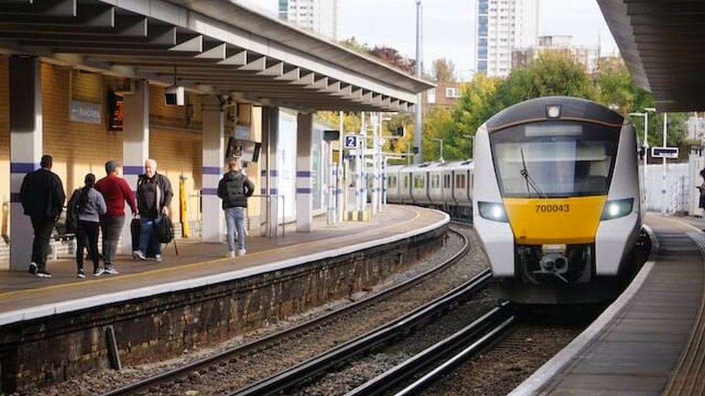
- Passenger vehicles
- minibuses
- Locomotives
- Power units of railway vehicles
- Passenger class wagon carriers
This standard defines the required space for manoeuvring guardrails and manoeuvring stands and provides references for the required space for handling side buffer screw connections. This standard defines steps, guardrails and their dimensions and clearance spaces for personnel access. It also defines dimensions and requirements for materials or design loads to meet the requirements for loads applied by personnel.
This standard also defines the general requirements for steps and handrails for access to external equipment, such as windshields, wipers or exterior lights.
For the purposes of this standard, the following definitions apply in addition to the terms and definitions given in EN 17343:
- Clearance refers to the defined free space required for the correct operation of devices and to ensure safety during handling.
- A step is a step with features defined for personnel use only.
- The maneuverer is the maneuvering personnel who couples and uncouples vehicles and directs movements.
- The maneuverer step is a special step used for the maneuver vehicle stand.
- A handrail is a railing with features defined for personnel use only.
- The maneuverer's guardrail is a special guardrail that is installed on the header under each bumper.
- A maneuvering stand is a maneuvering step used with a guardrail for the exclusive use of maneuvering personnel to allow the maneuverer to step outside the vehicle during maneuvering.
- Reserved areas refer to the defined free space required to ensure safe working conditions for maneuvering personnel during the assembly and separation of screw connections.
- A safe working position is a position that provides visibility for maneuvering personnel to direct driving during maneuvering operations. These positions can be: a maneuvering stand, a platform, a step with a corresponding handrail, the driver's cabin or the entrance of a passenger car with visibility in the direction of travel.
The general requirements for steps and handrails are described in this standard as follows:
- Steps and railings must withstand the loads applied by personnel.
- In order to be able to rely on the safety of the steps and guardrails, an appropriate stiffness must be provided. The corresponding stiffness criteria (permissible elastic deformation under load) for steps and guardrails are optional and must be defined in the specification.
- The following requirements must be proven by analysis or testing:
- The steps used as a safe working position for the maneuvering vehicle must be capable of withstanding separate effective forces of 2,0 kN vertically and 1,5 kN horizontally or longitudinally when applied by the personnel at any point, and these forces must not cause permanent deformation to itself or to its fasteners when applied by the personnel at any point.
- Other rungs must be capable of withstanding separate effective forces of 1,5 kN vertically and 1,5 kN horizontally or longitudinally when applied by personnel at any point, and these forces must not cause permanent deformation to the personnel or to the fasteners.
- Guardrails must be able to withstand a force of 1,5 kN applied by personnel at any point and in any direction without permanent deformation to themselves or their fixings.
- When demonstrated by testing, it is recommended that the component be preloaded and the maximum force applied at least twice to compensate for any residual stresses generated during manufacture. The results of final tests should not show permanent deformations.
- Railings must not have sharp edges. If the railings are rectangular, the corners must be rounded. Unless otherwise specified in this standard, the cross-sectional dimensions must be:
- For round shape: 20mm to 35mm
- For oval shape: minimum size of 12mm thick and 35mm wide and maximum size of 40mm
- Unless otherwise specified in this standard, guardrails must have a minimum clearance of 40 mm, which may be reduced to a minimum of 100 mm if necessary. Steps and guardrails used by personnel must be secured as follows:
- With positive locking
- With sufficient length and suitable self-locking bolts
- With high strength locking ring bolts
- Welded in accordance with EN 15085-1 standard
- All steps must be constructed with a non-slip surface and must not have sharp edges that could interfere with personnel's shoes.
- Steps or platforms used as a safe working position for the manoeuvring person, walkways and access steps to the platform and the driver's cab in shunting power units must be made of metal gratings that are not protected from the weather and can be covered with ice, and must meet the following criteria:
- Resistance to friction: The average value of the coefficient of friction measured in three directions (longitudinal, transverse and crosswise) shall reach the following minimum values: 0,65 in dry and wet (water) conditions, 0,30 in oily conditions. The coefficient of friction values shall be determined by means of a 80 mm × 100 mm moving plate to which a rubber pad with a hardness of 100 shore is glued. A weight of 75 kg shall be loaded on this plate. For measurements in water and oil, the grid shall be completely immersed.
- Grid structure: To ensure that the grids are sufficiently adapted to winter conditions, the ratio of free space to total area must be at least 50 percent. To determine this ratio, only openings through which a spherical object with a diameter of 10 mm and an area of at least 400 mm2 can pass are taken into account.
Among the numerous testing, measurement, analysis and evaluation studies that our organization has carried out for businesses in various sectors, with its trained and expert staff and advanced technological equipment, it also provides testing services defined in the standard “EN 16116-1 Railway applications - Design requirements for steps, guardrails and related access for personnel - Part 1: Passenger vehicles, minibuses and locomotives”.



