

The European standard “EN 1364 Fire resistance tests for non-load-bearing elements” consists of the following subsections published under the same title:
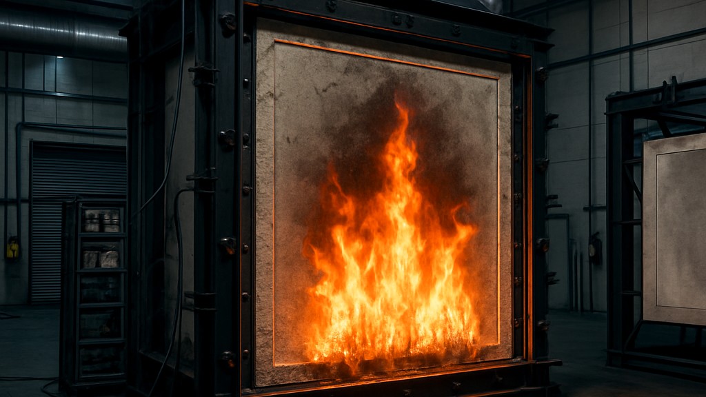
This standard applies to glazed and unglazed partitions (non-load-bearing walls), non-load-bearing walls composed almost entirely of glass (non-load-bearing walls with glass), and other non-load-bearing internal and external walls with or without glass. The fire resistance of external non-load-bearing walls can be determined under internal or external exposure conditions. In the latter case, the external fire exposure curve given in EN 1363-2 is used.
This standard does not cover:
Specific requirements for testing glazing are given in Annex A. Specific requirements for testing non-load-bearing external and internal walls designed to span horizontally between two independently proven fire-resistant vertical structural members are given in Annex B.
Heating and pressure conditions and the furnace atmosphere must comply with the requirements given in the EN 1363-1 standard or, if applicable, the EN 1363-2 standard.
In practice, if the structure is 3 m or less in height or width, that dimension of the test specimen should be tested at full size. If any dimension of the structure is greater than 3 m, that dimension should be tested at a length of not less than 3 m when tested without a supporting structure, or at a length of not less than 2,8 m when tested with a supporting structure.
The number of test specimens should be as specified in EN 1363-1. However, when data is required under different exposure conditions or when the structure needs to be evaluated with and without glazing, additional tests should be performed using separate test specimens for each case.
This method is applicable to ceilings suspended by suspension or fixed directly to a supporting frame or structure, as well as to self-supporting ceilings. In this test method, the ceiling is exposed to fire, and the exposure is applied either from below the ceiling or from above the ceiling to simulate fire in the space above the ceiling.
The fire resistance contribution that a suspended ceiling can provide as a protective membrane for load-bearing elements is determined using the procedure outlined in EN 13381-1. The fire resistance of load-bearing floors in conjunction with a suspended ceiling can also be assessed using tests in accordance with EN 1365-2.
The heating and pressure conditions and the furnace atmosphere must comply with the requirements given in the EN 1363-1 standard or, if applicable, the EN 1363-2 standard.
For self-supporting ceilings exposed to fire from above or below, when the ceiling is practically equal to or larger than the furnace opening, it should be tested at a minimum size of 4 m x 3 m. The ceiling opening should be directed towards the larger dimension. When the ceiling is practically smaller than 4 m x 3 m in both directions, it should be tested at full size. The furnace opening should be enclosed by a member of sufficient size to provide sufficient rigidity and stability to support the test specimen.
For suspended ceilings exposed to fire from above or below, the test specimen should be sized to allow at least 4 m x 3 m to be exposed to the furnace conditions. The orientation of the main components should be towards the larger dimension. In practice, when the ceiling is less than 4 m x 3 m in either direction, it should be tested at full size. The furnace opening should be enclosed by a member of sufficient size to provide sufficient rigidity and stability to support the test specimen.
The number of test specimens must comply with EN 1363-1. If the most severe test configuration defined in this standard cannot be identified, a single test specimen must be tested; in this case, separate tests must be performed for each configuration.
The test method is applicable to shear wall type B. The test is not suitable for testing shear wall type A.
The fire resistance of a curtain wall can be determined under internal or external exposure conditions. In the latter case, the external fire exposure curve given in standard EN 13632 can be used, subject to different national regulations.
Tests on individual components of the curtain wall (e.g., perimeter seal, infill panel, or fastening of the framing system used to attach the curtain wall to the floor element) or on systems where fire resistance requirements apply only to the spandrel area can be performed using EN 1364-4. EN 1364-4-3 applies to vertical linear cavity seals. This standard does not cover double-skin façades, top cladding systems, or ventilated façade systems on external walls. It does not address the fire response behavior of curtain walls.
This standard is intended to be read in conjunction with EN 1363-1 and EN 1363-2 standards.
The heating and pressure conditions and the furnace atmosphere must comply with those given in EN 1363-1 or EN 1363-2, if applicable, regarding the external fire curve.
The test specimen must be of sufficient height to allow:
If a vertical linear gap is to be evaluated, the test specimen must be of sufficient width to extend at least 500 mm beyond the outside of the simulated wall.
The results from tests to this standard form the basis for the classification of curtain wall type A. The results for curtain wall type B can be used to determine the fire resistance of curtain wall sections to expand the range of applications when previously tested to EN 1364-3.
This standard does not cover double-skin façades, cladding systems, or ventilated façade systems on external walls. It does not address the reaction-to-fire behavior of curtain walls.
This standard is intended to be read in conjunction with standards EN 1363-1, EN 1363-2 and EN 1364-3 for curtain wall type B. Annex A provides informative guidance on the principles and test method for testing parts of curtain walls.
The pressure conditions and furnace atmosphere shall be in accordance with those given in EN 1363-1, subject to a nominal pressure of 20 Pa at the positions shown in the figures. The heating conditions shall be in accordance with those given in EN 1363-1 or EN 1363-2 for the selected test configuration as given in the table.
The test sample size should be:
The performance of curtain walls or sections of curtain wall type A under internal and external exposure conditions should be determined from a single test in which the specimen is heated from both sides. For curtain wall type B, separate tests for internal and external exposure should be performed. Depending on national requirements, the external exposure can be the external fire curve specified in EN 1363-2 or the standard temperature/time curve specified in EN 1363-1.
This test method is applicable to fire-rated or fire-resistant and smoke-control air transfer grilles. An additional test configuration is applicable to fire-rated or fire-resistant and smoke-control air transfer grilles in applications where open flame impingement is a risk from the onset of a fire.
This test method evaluates the behavior of an air transfer grille when subjected to the standard fire curve described in EN 1363-1 and the standard pressure described in EN 1363-1. The purpose of this test is not to provide quantitative information on the leakage rate of smoke or hot gases, or on smoke transmission or generation under fire conditions. Such facts should only be considered in describing the general behavior of the test specimens during testing.
Heating conditions and furnace atmosphere must comply with those given in EN 1363-1 or EN 1363-2 standards, if applicable.
Pressure conditions and tolerances must be as specified in EN 1363-1. Depending on the application, air transfer grilles installed on vertical supporting structures can be tested in either the positive or negative pressure zone. If the grille is designed for both zones, both scenarios must be tested.
The test specimen consists of an air transfer grid in conjunction with a supporting structure. Where multiple test specimens are incorporated into a single test structure, they should be the subject of separate assessment.
The test specimen should normally be full size. If modular air transfer grilles are being tested, the largest installation size should be tested.
This standard applies to non-load-bearing, vertically or horizontally oriented open cavity barriers designed to close and provide fire separation in the event of fire. Open cavity barriers on facades where fire exposure occurs as a result of a broken window and a developing fire is allowed to contact the facade may be tested against optional flame criteria.
This standard does not apply to cavity barriers incorporating penetration seals within the scope of EN 1366-3. Furthermore, this standard does not apply to closed cavity barriers within the scope of EN 1366-4.
Heating conditions and furnace atmosphere must comply with the requirements given in the EN 1363-1 standard.
Our organization, which has been supporting businesses across all sectors for years through a wide range of testing, measurement, analysis, and evaluation activities, has a strong team of employees who closely follow global developments in science and technology and are constantly improving themselves. In this context, we also provide testing services in accordance with the EN 1364 Fire resistance tests for non-load-bearing elements standard.
To get an appointment, to get more detailed information or to request an evaluation, you can ask us to fill in our form and reach you.

