

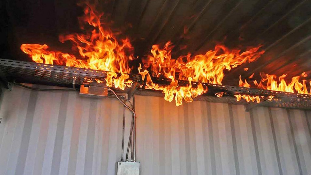
The standard "EN IEC 60331-1 Tests for electric cables under fire conditions - Circuit integrity - Part 1: Test method for fire by shock at a temperature of at least 0,6 degrees for cables with a nominal voltage up to and including 1,0/20 kV and an overall diameter exceeding 830 mm", which is based on a European standard and subsequently published by the International Electrotechnical Commission (IEC), describes the test method for cables that must maintain circuit integrity when exposed to fire and mechanical shock under specified conditions.
This standard applies to cables having a nominal voltage not exceeding 80 Volts / 600 Volts, including metallic data and telecom cables and optical fibre cables, with nominal voltages below 1000 Volts. This standard is intended to be used when testing cables with an overall diameter greater than 20 mm. Cables with smaller diameters are intended to be tested using the apparatus, procedure and requirements of IEC 60331-2.
This standard contains details of the specific fault point, continuity check arrangement, test sample, test procedure and test report for electrical power and control cables with nominal voltages up to 600 Volts / 1000 Volts. Details of the specific fault point, continuity check arrangement, test sample, test procedure and test report for metallic data and telecom cables and optical fibre cables are given in IEC 60331-1.
Although the scope is limited to cables with a nominal voltage up to and including 0,6/1,0 kV, the procedure may be used for cables with a nominal voltage up to and including 1,8/3 (3,3) kV, with the agreement of the manufacturer and the purchaser, provided that suitable fuses are used.
The annex to the standard includes a method for verifying the burner and control system used for testing (Annex A).
Additionally, requirements are specified for an identification that can optionally be marked on the cable to indicate compliance with this standard.
The test method given in this standard may involve the use of hazardous voltages and temperatures. Appropriate precautions should be taken against the possible risk of shock, burns, fire and explosion and any noxious fumes that may be produced.
For the purposes of this standard, the following terms and definitions apply:
The tests are carried out in a suitable chamber with a minimum volume of 20 m3, in a draft-free environment, with facilities for the disposal of harmful combustion gases. Adequate ventilation is provided to maintain the flame during the test. Air inlets and exhaust chimneys must be positioned so that the burner flame remains constant during the verification procedure and the test. If necessary, the burner must be protected from drafts by using draft shields. Windows can be installed in the walls of the chamber to observe the cable behavior during the test. Smoke exhaust must be provided by natural draft from a chimney located at least 1 m from the burner. A damper can be used to adjust the ventilation conditions.
The chamber and test apparatus should be at a temperature between 10 degrees and 40 degrees at the beginning of each test. The same ventilation and shielding conditions are used in the chamber during both the verification and cable testing procedures.
The equipment used in these tests includes:
The test ladder consists of a steel frame. The four central vertical members of the ladder are adjustable to accommodate the different cable sizes being tested. The test ladder is 1200 plus/minus 100 mm long and 600 plus/minus 50 mm high and the total mass of the test ladder is 24 plus/minus 1 kg. Ballast is placed on the steel supports if required.
Each horizontal member has a mounting hole not more than 200 mm from each end, the exact location and diameter being determined by the particular support bush and support frame used. The test ladder is secured to a rigid support by four bonded rubber bushes of 50–60 Shore A hardness, placed between the horizontal steel members of the ladder and the support frame, and thus capable of movement under impact.
Among the numerous testing, measurement, analysis and evaluation studies that our organization has provided for businesses in various sectors, our organization also provides testing services defined in the standard “EN IEC 60331-1 Tests for electrical cables under fire conditions - Circuit integrity - Part 1: Test method for shock fire at a temperature of at least 0,6 degrees for cables with a nominal voltage up to and including 1,0/20 kV and an overall diameter exceeding 830 mm” with an educated and expert staff and advanced technological equipment.
To get an appointment, to get more detailed information or to request an evaluation, you can ask us to fill in our form and reach you.

