

The design of any electrical product must consider the risk of fire and its associated potential hazards. The goal of component, circuit, and product design, as well as material selection, is to reduce to acceptable levels the risks of fire, reasonably foreseeable abnormal use, failure, or malfunction during normal operating conditions.
The EN IEC 60695-1-10 standard was developed together with the companion EN IEC 60695-1-11 standard to provide guidance on how to achieve this. The main objectives of the EN IEC 60695-1-10 and EN IEC 60695-1-11 standards are to:
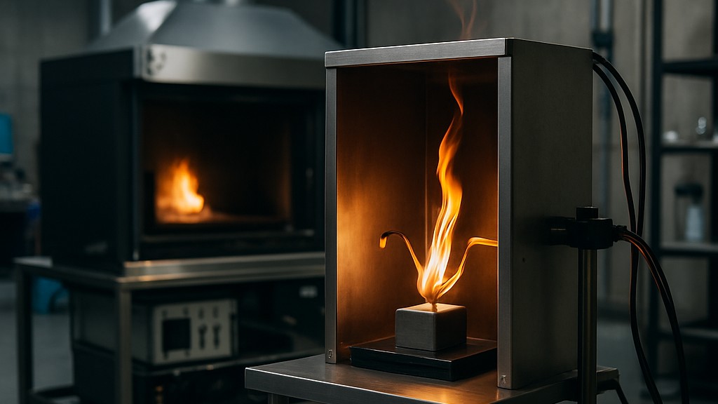
Secondary objectives of these standards include minimizing flame spread beyond the product enclosure and minimizing the harmful effects of fire residues such as heat, smoke, toxicity, or corrosiveness. Fires in electrotechnical products can also be initiated from external, non-electrical sources. Such considerations should be considered in the overall fire risk assessment. In electrotechnical equipment, overheated metal parts can act as ignition sources. Glow-wire tests use a glow-wire to simulate such an ignition source. EN IEC 60695-2-10 provides recommendations for glow-wire testing apparatus and describes a common test procedure for tests applicable to end products and materials.
The standard "EN IEC 60695-2-10 Fire hazard testing - Part 2-10: Glow/hot wire based test methods - Glow wire apparatus and common test procedure", which is based on a European standard and subsequently published by the International Electrotechnical Commission (IEC), describes the glow wire apparatus and common test procedure to simulate for short periods the effects of thermal stresses that can be produced by heat sources such as glowing elements or overloaded resistors in order to assess the fire hazard by a simulation technique.
The test procedure described in this standard is a common test procedure designed for small-scale tests using a standardized electrically heated wire as the ignition source. It is a common part of the test procedures applied to end products and solid electrical insulating materials or other solid combustible materials. Detailed descriptions of each test procedure are included in standards IEC 60695-2-11, IEC 60695-2-12, and IEC 60695-2-13.
The glow wire used in these tests was formed from nickel/chromium (minimum 77 percent nickel, 20 percent plus or minus 1 percent chromium) wire with an overall diameter of 4,00 mm plus or minus 0,07 mm before bending. The dimensions of the glow wire loop are as shown in the standard. Before using a new glow wire for a test run, it should be annealed for a total of at least 10 hours by subjecting it to a current of at least 120 A. The total annealing time can be obtained cumulatively. To prevent damage, no thermocouple should be installed during annealing. At the end of annealing, the depth of the thermocouple pocket hole should be verified. The temperature of a new, unannealed glow wire decreases gradually during the first few hours of exposure to current. After a period of time, the temperature reaches equilibrium.
The test setup should be designed so that the glow wire is held in a horizontal plane and exerts a force of 0,95 N plus/minus 0,10 N on the test specimen during the application of the glow wire. The force should be maintained at this value as the glow wire and the test specimen are moved horizontally toward each other. The distance the tip of the glow wire penetrates and passes through the test specimen should be limited to 7 mm plus/minus 0,5 mm. The test setup should be designed so that burning or glowing particles falling from the test specimen can fall unimpeded onto the substrate. Two typical examples of test setups are shown in the figures.
The glow wire is heated by a simple electrical circuit. There should be no feedback mechanism or circuit to maintain the temperature. The power supply for the glow wire tester should be a stabilized voltage source (plus or minus 2 percent rms). The test circuit should include a current meter that displays the true rms value with a maximum accuracy of 1,0 percent. Because of the high currents involved, it is important that all electrical connections to the glow wire be capable of carrying the current without affecting the circuit's performance or long-term stability. A sufficient contact area (typically at least 60 mm2 at each end) is required for the constant, loss-free current required for the test. The glow wire-stud connection should be securely screwed, soldered, or brazed between the glow wire and the studs.
The temperature of the glow wire tip should be measured with a Class 1 mineral-insulated, metal-sheathed, fine-wire thermocouple with an insulated junction. The thermocouple should have an overall nominal diameter of 1,0 mm. Thermocouple wires should be suitable for continuous operation at temperatures up to 960°C. The weld point should be located within the sheath as close as possible to the tip. The sheath should be made of a metal that can withstand continuous operation at a temperature of at least 1050°C.
The thermocouple is inserted into a pocket hole drilled behind the glow wire end and secured securely. The pocket hole should be the smallest diameter that will accommodate the inserted thermocouple to reduce contamination during testing. Thermal contact between the thermocouple tip and the drilled hole tip must be maintained. Care must be taken to ensure that the thermocouple can track changes in size caused by heating at the glow wire end. The device used to measure thermocouple voltages can consist of any commercial digital thermometer with a built-in reference port. Other temperature measuring devices can be used, but in cases of dispute, the thermocouple method should be used.
Our organization, which has been supporting businesses across all sectors for years through a wide range of testing, measurement, analysis, and evaluation activities, boasts a strong team of employees who closely follow global developments in science and technology and are constantly improving themselves. In this context, we also provide testing services in accordance with the standard "EN IEC 60695-2-10 Fire hazard testing - Part 2-10: Glow/hot wire-based test methods - Glow wire device and general test procedure."
To get an appointment, to get more detailed information or to request an evaluation, you can ask us to fill in our form and reach you.

