

The standard "ASTM E190 Standard Test Method for Guided Bend Testing of Welds for Ductility," developed by the American Society for Testing and Materials (ASTM), describes a guided bend test method for determining the strength and ductility of welds in ferrous and nonferrous products. Defects not visible on X-rays may appear on the surface of a specimen when subjected to gradual local overstress.
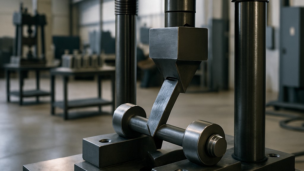
The specimen is bent in a "U"-shaped die by applying a force centrally to the weld bead on a flat specimen supported at two locations equidistant from the line of force application. The specimen is forced into the die by a piston shaped to produce the desired contour. The convex surface of the bent specimen is examined for cracks or other obvious defects.
The directed bend test described in this test method is used to evaluate the quality of welds with respect to ductility as evidenced by their ability to resist cracking during bending.
Specimens commonly used for guided bend testing are rectangular specimens machined from plates and pipes. The weld face of a flat specimen contains the larger portion of the weld material, while the opposite side is called the weld root surface. Specimen types are as follows:
During testing, guided bend specimens are bent in a test fixture that substantially conforms to the shape specified in the standard. Transverse specimens are placed in the fixture's mold element with the weld at midspan. Face bend specimens are placed with the weld facing the cavity; root bend specimens are placed with the root of the weld facing the cavity; and side bend specimens are placed with the side showing the larger imperfections facing the cavity. If no significant imperfections are present, either side may be selected.
Any suitable means can be used to move the piston relative to the die, but it must be stationary and there must be no significant lateral movement. Force is applied until the sample forms a "U" shape and a 3,2 mm diameter wire cannot be inserted between the sample and any point on the curvature of the jig piston element. However, this would be possible if the sample failed prematurely.
Ductility of welds refers to the ability of a welded joint to deform plastically (flex or bend) without fracture when subjected to stress. It is a critical mechanical property that indicates how well a welded material can handle deformation under tensile or bending forces, particularly in dynamic or highly stressed environments.
In welding, ductility measures how much a welded joint can stretch or bend before fracture. Higher ductility indicates a greater ability to absorb stress without cracking.
Ductility in welds is important for the following reasons:
Factors affecting weld ductility are:
The following test methods are generally used to determine weld ductility:
This standard is widely applied to bridges, ships, pipelines, aircraft, and pressure vessels where deformation without failure is critical, as well as environments where thermal expansion or heavy dynamic loads are critical.
Our organization, which has been supporting businesses across all sectors for years through a wide range of testing, measurement, analysis, and evaluation activities, has a strong team of employees who closely follow global developments in science and technology and are constantly improving themselves. In this context, we also provide testing services in accordance with the "ASTM E190 Standard Test Method for Guided Bend Testing of Welds for Ductility."
To get an appointment, to get more detailed information or to request an evaluation, you can ask us to fill in our form and reach you.

