

The European standard "EN 12089 Thermal insulation products for building applications - Determination of flexural behavior" describes the equipment and procedures used to determine the flexural behavior of full-size products (Method A) and test specimens (Method B) under three-point loading. These methods are applicable to thermal insulation products.
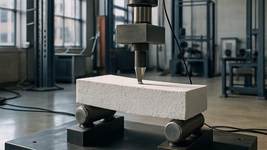
These tests are designed to determine the flexural strength of products and their deflection under a specified load. This method can be used to determine the product's resistance to bending stresses during transportation and application.
For the purposes of this standard, the following terms and definitions apply:
The test method consists in applying a force, in an axial direction, via a loading edge to the surfaces of a square-cut rectangular test specimen placed on two supporting edges at a specified speed. The force is applied at test speeds at a position between the supporting positions.
The testing machine used in these tests is a machine with a loading edge and adjustable support edges suitable for the relevant force and displacement range. The moving head must operate at a constant travel speed. Test specimen supports must consist of two adjustable cylindrical support edges placed parallel to each other and in the same horizontal plane. The diameter of the supports must be 80 mm plus/minus 3 mm or 30 mm plus/minus 3 mm. The length of the support edges must be at least equal to the width of the test specimens. The clearance between the support edges must be adjustable within the range of 300 mm to 1200 mm (Method A) or 200 mm to 500 mm (Method B).
The test specimen loading edge should be the same shape and dimensions as the support edges. The loading edge should be positioned parallel to and centered on the support edges.
For products that may be subject to crushing due to loading and support edges, steel load distribution plates with a minimum thickness of 1 mm should be used. The width of the distribution plates should be 30 mm plus/minus 1 m, and their length should be at least the width of the test specimen.
Displacement and force measuring devices are also used in the tests. The testing machine must be equipped with a system that allows continuous measurement of the displacement of the moving loading edge to an accuracy of plus or minus 5 percent or plus or minus 1/2 mm, whichever is less. The measured displacement is the same as the deflection of the test specimen.
A force sensor should be fixed to the loading edge to measure the force generated by the test specimen's reaction against the edges during testing. This sensor should be such that its deformation during the measurement process is negligible compared to the measured value or can be considered in the calculation. It should also allow for continuous force measurement at all times, with readings accurate to within plus or minus 1 percent. A device is used to simultaneously record force and deflection to obtain the required force-deflection curve.
In Method A, the test specimen is a full-size product. It will be a square-cut rectangle with the following dimensions:
In Method B, the test specimen shall be a square-cut rectangle with the following dimensions:
Other dimensions of the test sample may be specified in the relevant product standard or any other European technical specification or agreed upon between the parties.
The number of test samples must be as specified in the relevant product standard or other European technical specification. In the absence of such a specification, a minimum of three test samples must be used. In the absence of a product standard or other European technical specification, the number of test samples may be agreed upon between the parties.
If the direction of the bending force on the product during application is unknown or if the two main surfaces of the product have different surface coatings, primers or coatings, additional sets of test specimens must be used.
When preparing test samples, cutting of test samples should be done using methods that do not alter the original structure of the product. Any coating, primer, or coating should be preserved.
Test samples must be stored at 23 degrees plus/minus 5 degrees for at least 6 hours. In case of disagreement, they must be stored at 23 degrees plus/minus 2 degrees and 50 percent plus/minus 5 percent relative humidity for at least 6 hours for the period specified in the relevant product standard.
Tests should be conducted at 23 degrees plus/minus 5 degrees. In case of disagreement, they should be conducted at 23 degrees plus/minus 2 degrees and 50 percent plus/minus 5 percent relative humidity.
In Method A, the length and width for full-size products are measured according to EN 822 and the thickness according to EN 823. In Method B, the length, width, and thickness of the test samples are measured to an accuracy of 1 percent according to EN 12085.
The clearance between the support edges must be within plus/minus 0,5 percent of:
Other clearances may be given in the relevant product standard or by agreement between the parties.
The test specimen is placed symmetrically on the support edges, with the loading direction perpendicular to the longitudinal axis of the specimen. The testing machine speed is set at 10 mm/min with a tolerance of plus or minus 10 percent. The force-deflection curve is recorded, and the maximum force achieved is noted. The fracture pattern of the specimen is recorded.
Our organization, which has been supporting businesses across all sectors for years through a wide range of testing, measurement, analysis, and evaluation activities, has a strong team of employees who closely follow global developments in science and technology and are constantly improving themselves. In this context, we also provide testing services in accordance with the EN 12089 Thermal insulation products for building applications - Determination of flexural behavior standard.
To get an appointment, to get more detailed information or to request an evaluation, you can ask us to fill in our form and reach you.

