ISO 24338 Laminate Floor Coverings - Determination of Abrasion Resistance
The International Organization for Standardization (ISO) standard, "ISO 24338 Laminate floor coverings - Determination of abrasion resistance," describes Method A and Method B for measuring the abrasion resistance of laminate flooring elements. These test methods measure the abrasion resistance of the surface layer.
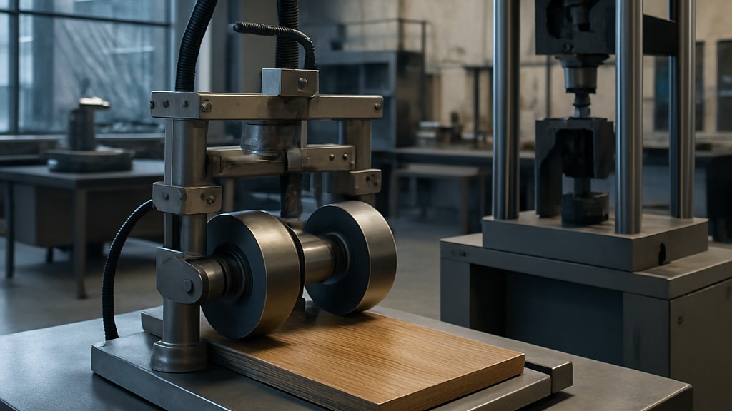
According to Method A, abrasion is determined by rotating a test specimen in contact with a pair of loaded cylindrical wheels covered with specified abrasive paper. According to Method B, abrasion resistance is assessed by abrading the surface of test pieces with a specified abrasive applied by two loaded wheels. Both methods measure the number of revolutions of the test specimen required to cause a specified degree of wear. The precision of these methods is unknown. When interlaboratory data become available, a statement of precision will be added to the standard.
The main equipment used in these tests are:
- Testing machine (for Method A and Method B)
- Test specimen holder (for Method A and Method B): The disc-shaped holder with a diameter of approximately 105 mm rotates in the horizontal plane with a permissible deflection of plus/minus 2 mm/m at a frequency of 60 plus/minus 2 revolutions per minute, and the test specimen can be clamped by a clamping screw.
- Holding and lifting assembly (for Method A and Method B): The holding and lifting assembly for the abrasive wheels is designed to exert a force of 5,4 N plus/minus 0,2 N (Method A) or 10 plus/minus 0,2 N (Method B) on the test specimen for each wheel. For Method B, a counterweight of 150 plus/minus 3 g is required to balance the mass of the leather abrasive wheel. A second pair of leather abrasive wheels may be used for this purpose. Calibration and maintenance of Taber abrasive arms shall be carried out in accordance with Appendix A.
- Rubber-coated abrasive wheels (for Method A): Two cylindrical rubber-coated wheels, 12,7 mm plus/minus 0,1 mm wide and 50 mm in diameter, which rotate freely about an axis. The curved surface of the wheels, to a depth of 6 mm, shall be made of rubber with a hardness of 65 plus/minus 3 IRHD (according to ISO 48) or 65 plus/minus 3 Shore A (according to ISO 7267-2). Measurements and a description of a suitable measuring setup are shown in Appendix B. The inner surfaces of the wheels shall be 52,5 mm plus/minus 0,2 mm from the centerline of the abrasive head and equally spaced 26,25 mm plus/minus 0,10 mm, and the axis of the wheels shall be 19,05 mm plus/minus 0,3 mm from the vertical axis of the test specimen holder. It is important to ensure that abrasive wheels are in good condition, as variations in flatness, hardness, smoothness, roundness, and width can significantly affect test results. It is crucial that the dimensions and tolerances in this standard are met, as deviations can lead to errors exceeding 100 percent.
- Sandpaper strips (for method A): Abrasive strips measuring 12,7 mm plus/minus 0,1 mm wide in the machine direction and approximately 160 mm long should be used. These should meet the following requirements: weight between 70 g/m² and 100 g/m², particle size that will pass through a 100 μm sieve and retain on a 63 μm sieve, open-coated 180-grit aluminum oxide, glue-bonded, adhesive backing.
- Calibration plates (for Method A): Rolled zinc plate with a thickness of 0,8 mm plus/minus 0,1 mm and a Brinell hardness of 48 plus/2 should be used (according to ISO 6506-1, ball diameter 5 mm and load 360 N). For type approval or verification purposes, the zinc plate should be used for no more than 10 calibrations per side.
- Suction assembly (for Method A): Two suction nozzles should be positioned to cover the worn area of the test specimen. One nozzle should be positioned between the wheels, the other directly opposite. The nozzle centers should be 77 mm apart and 2 mm plus/minus 0,5 mm from the surface of the test specimen. With the nozzles closed, a vacuum of 1,5 to 1,6 kPa should be created.
- Revolution counter (for Method A and Method B): A revolution counter is used to record the number of revolutions of the sample holder.
- Grit feeder and accessories (for Method B only)
- In general: A sand feeder should have a minimum storage capacity of approximately 200 g of sand, and the top and bottom of the feeder should be openable. The bottom opening should be positioned 10 mm plus or minus 1 mm above the surface of the test piece, be 16 mm plus or minus 1 mm long, and be 3,18 mm plus or minus 0,38 mm wide. The length of the bottom opening should be radial to the test specimen holder. A device in the sand feeder should ensure a steady flow. The feeder should also be equipped with a device that allows for immediate stopping of the feed if necessary.
- Vacuum cleaning device: After the abrasive grit has passed under the wheel (in the direction of rotation), a suction nozzle positioned 3 mm plus/minus 2 mm above the rail to be abraded should be placed in the axial vertical plane of the left wheel. The vacuum power should be adjusted to a level that removes all dust and debris.
- Abrasive material: Abrasive grain (bauxite-based, electric arc furnace aluminum oxide) with a chemical composition according to the table should be used. The specific gravity of the abrasive mineral is 3,96 g/cm3 and the Knoop hardness is 21 kN/mm2. The medium grain form of the mineral has a bulk density between 1,51 g/cm3 and 1,62 g/cm3 according to FEPA standard 44-D. The particle size distribution varies between 45 µm and 75 µm, with a reduced fines fraction determined according to FEPA standard 42-D according to the table. The abrasive material should be stored in a dry place and used only once. It should not be sifted before use.
- Leather grinding wheels: Two cylindrical wheels, nominally 44,4 mm in diameter and 12,7 mm wide, that rotate freely about their axes. The wheels are fitted with a leather strip 12,7 mm wide plus or minus 0,1 mm and a minimum thickness of 1,5 mm. The total diameter of the leather-striped wheels must not exceed 52 mm and must not be less than 46 mm. The hardness of the leather strips must be suitable for the purpose. It is measured using a Type A Shore durometer according to ISO 868 with the following deviation: Shore-A hardness is measured at four points in the centre of the tread of the abrasive wheels. Leather hardness is suitable if all results are within the range A/1:85 to A/1:95. The distance between the inner surfaces of the wheels should be 52,5 mm plus or minus 0,2 mm, and their common axis should be set at a nominal distance of 19,05 mm plus or minus 0,3 mm from the axis of the specimen holder. The axis of rotation of the test piece should be equidistant from the two wheels. Before testing, new abrasive wheels must be preconditioned: New wheels are subjected to an initial 2000 cycle test following the procedure described here.
- Stopwatch: Stopwatch with accuracy of plus/minus 0,1 seconds.
- Grit collecting container: A container of known mass to collect the grit when calibrating the grit feeder.
- Calibration plates: Calibration plates made of cell cast acrylics with Rockwell hardness M 94 according to ASTM D785 standard.
- Transparent template to assess the wear of the worn area: A transparent template should be used to visually observe the wear.
- Additional materials or equipment (Method A and Method B)
- Weighing equipment: To determine the mass loss of zinc plate by sandpaper or to calibrate the grit flow of abrasive material, weighing equipment with an accuracy of plus/minus 1 mg is needed.
- Conditioning room: The conditioning room must be able to maintain a standard climate of 23 degrees plus/minus 2 degrees and a relative humidity of 50 percent plus/minus 5 percent.
Each method requires three randomly selected laminate flooring elements. A test sample of approximately 100 mm x 100 mm is taken from each element:
- A sample located 10 mm from the left short edge of the first element
- A sample located in the middle of the second element
- A sample located 10 mm from the right short edge of the third element
Machined edges and machined surfaces should be avoided on specimens. If specimen thickness exceeds 8 mm, the specimens should be milled to a depth of 7,5 mm plus/minus 0,5 mm from the back side to ensure horizontal loading on the abrasive arms. It is essential to ensure that the specimens are properly flat and parallel after milling.
Our organization, which has been supporting businesses across all sectors for years through a wide range of testing, measurement, analysis, and evaluation activities, boasts a strong team of employees who closely follow global developments in science and technology and are constantly improving themselves. In this context, we also provide testing services in accordance with the ISO 24338 Laminate Floor Coverings - Determination of Abrasion Resistance standard.



