EN 12618 Products and Systems for the Protection and Repair of Concrete Structures - Test Methods
The European standard “ EN 12618 Products and systems for the protection and repair of concrete structures - Test methods ” consists of the following sub-sections published under the same title:
- The standard “EN 12618-1 Part 1: Adhesion and elongation capacity of injection products with limited ductility” describes the reference procedure for determining the adhesive bond capacity and elongation capacity of injection products intended for the ductile filling of cracks and voids.
In principle, the extensibility and tensile bond strength of the product (and the effect of crack width on these parameters) are determined after injection into cracks of different widths and under three crack moisture conditions (dry, wet, and waterlogged). Elongation and bond strength tests are performed at 3°C plus/minus 2°C.
The equipment used in these tests includes:
- Tensile testing machine: The laboratory where these tests are performed must be equipped with a testing machine that complies with the requirements of EN 196-1. The testing machine must be equipped with a self-aligning load application to ensure axial tensile loading of the specimen and must have a controlled environment cabinet capable of maintaining constant temperatures of plus/minus 3 degrees Celsius. The tensile force must be at least 50 kN with an adjustable speed of 0,01 mm/min.
- Mold: The steel mold consists of:
- Top steel plate provided with four M 12 threaded bolts, four M 16 galvanized threaded bolts, hexagon head screws and an opening for concrete, grooves for steel sheets
- Lower steel plate provided with four M 12 threaded bolts, four M 16 galvanized threaded bolts and one 24 screw, grooves for steel sheets
- Two large and two small steel plates as side coverings
- Three M8 threaded pipes and nuts with steel studs to provide injection product inlet, ventilation and pressure control
- Three connecting plates, hexagon socket screws
- Eight M16 threaded bolts and twenty M16 nuts to connect the upper and lower steel plates
- A rubber strip
- A crown
- X-Y recorder: Capable of displaying load-deformation curves. The deformation base must be read with an accuracy of 0,001 mm.
- Displacement transducer: The displacement transducer must provide continuous recording of the deformation with an accuracy of 0,001 mm.
- Measuring plate displacement meter: This equipment should measure a measuring length of approximately 100 mm with an accuracy of 0,001 mm.
- Injection equipment: The concrete cube contains three injection packers with an internal diameter of 2-3 mm. The packer openings are closed with valves. The manufacturer specifies the mixing equipment, injection pump, and packer type.
- Pressure gauge: A pressure gauge suitable for measuring pressures up to 6 MPa with an accuracy of 0,05 MPa.
EN 12618-2 Part 2: Determination of adhesion of injection products with or without thermal cycling - Adhesion by tensile bond strength" describes a test method for determining the adhesion of injection products to hydraulic concrete. This method is applicable to polymer and cementitious injection products.Injection can be performed on dry, damp, wet cracks, or with water flowing through them. Tensile bond testing should always be performed after the appropriate cure time under standard test conditions detailed below, but it can also be performed on another set of samples after a period of artificial aging by thermal cycling. This method can provide an opportunity for subjective assessment of injectability.
This test is based on the principle of tensile testing of composite specimens in sandwich, concrete/injection product/concrete form. These composite specimens are obtained by cutting or coring a composite test piece prepared by injecting the product into an artificial crack with controlled moisture content (dry, damp, wet, or submerged). The artificial crack is created by placing two concrete slabs face to face. This artificial crack is preferred to natural cracks produced by splitting because it allows better control of the contact area between the injection mortar and the concrete substrate, which is crucial for the measured load. The standard test conditions are a temperature of 21°C (plus/minus 2°C) and a relative humidity of 60% (plus/minus 10%).
The equipment used in these tests includes:
- Tensile testing machine: Equipment must have sufficient tensile capacity to cause the tensile bond of the specimen to fail, as per EN 24624. Accuracy must be within plus/minus 2 percent. A 10 kN capacity is sufficient for most applications. Tensile equipment must be capable of applying loads in accordance with EN 24624 and must be equipped with a measuring device that displays the applied force using an analog or digital system. The measuring device must record the maximum applied force, i.e., the failure load.
- Loading fixtures (dollys): Circular dollies with a diameter of 50 mm plus or minus 0,5 mm or square dollies with a diameter of 50 mm x 50 mm plus or minus 0,5 mm. Dollies shall be constructed of steel at least 20 mm thick or aluminum at least 30 mm thick. On the side where the adhesive will be applied, the dolly shall be flat with a tolerance of 0,1 mm per 50 mm length. Dollies shall be equipped with a means for attaching tensile testing equipment that allows the load to be applied perpendicular to the surface being tested without applying bending or shearing forces to the test area.
- Adhesive for bonding dollies to composite test pieces and three sides of sheets. Two-component epoxy, polyester or acrylic adhesives have been found suitable.
- Links for connecting dollies to the testing machine. These should be of the self-aligning type, i.e. fitted so that they self-align when any load is applied to the fixed and movable elements respectively, so that the axis of the test specimen coincides with the line of force provided through the centre line of the linkage assembly.
- Diamond core drill and barrel capable of drilling 50 mm plus/minus 0,5 mm cores. The core barrel should have a cutting edge that projects 1,5 mm plus/minus 0,5 mm from the cylinder to minimize lateral forces applied to the test area.
- Saw for cutting specimens. The saw should have a diamond or silicon carbide cutting edge and be capable of cutting specimens to the specified dimensions without overheating or shock.
- Conditioning chamber or cabinet capable of keeping the composite test piece and test samples at the specified temperature and relative humidity and, if necessary (for test samples only), achieving the thermal aging cycle specified below.
- Injection equipment including mixer, pressure vessel or injection pump (manual or electric injection hoses, injection nozzles/packers).
- The caulking or sealing compound to seal the side where the injection takes place and where any injection nozzles are installed is selected by the supplier of the injection product.
- 1000 x 500 x 40 mm concrete slabs cast from concrete specified in standard EN 1766. Sub-surfaces must be sufficiently flat to ensure that the gap width is kept within the permitted 30 percent tolerance.
- Pressure gauges: The injection unit should be equipped with a nozzle pressure gauge to measure the injection pressure. The pressure gauge should be constructed so that no mortar enters the gauge.
- Grinding equipment for removing adhesive from used cars.
- Vernier calipers with an accuracy of not less than 0,1 mm.
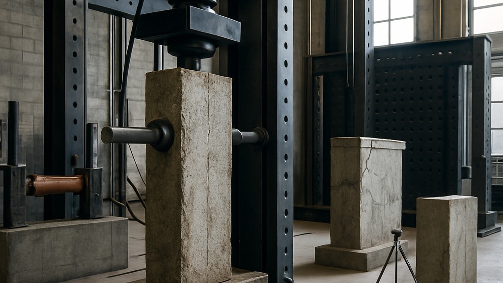
The standard “EN 12618-3 Part 3: Determination of the bond strength of injection products with or without thermal cycling - Oblique shear method” describes the method for determining the oblique shear bond strength of all injection products designed to restore the integrity of cracked concrete and covered by the EN 1504-5 standard.This method can be performed on cracks that are dry, damp, wet, or have water flowing through them. It should always be performed after the appropriate curing period under the standard test conditions detailed below, but it can also be performed on another set of samples after a period of artificial aging by thermal cycling.
While testing of the repaired crack is normally done with short-term static load, it can also be performed as a creep test with long-term static load or as a dynamic test by applying cyclic load.
The principle of this test is a compression test of a restored concrete prism, oriented at a 30-degree angle to its major axis. The joint was created by grouting a straight-line crack in the concrete. Therefore, the joint is subjected to a combination of shear and compressive stresses. The result is presented as the compressive strength of the composite prism (along with observations regarding the failure mode) because it can be easily correlated with conventional concrete evaluation and design procedures.
Test specimens are produced by cutting prisms from concrete slabs that have been controlled-split and repaired by injecting the product or system being tested. Control specimens of the concrete used in the slab preparation are similarly prepared and tested to provide comparative information.
Our organization, which has been supporting businesses across all sectors for years through a wide range of testing, measurement, analysis, and evaluation activities, has a strong team of employees who closely follow global developments in science and technology and are constantly improving themselves. In this context, we also provide testing services in accordance with the EN 12618 "Products and systems for the protection and repair of concrete structures - Test methods" standard.



