

The ASTM E2584 Standard Practice for Thermal Conductivity of Materials by Thermal Capacitance (Slug) Calorimeter, developed by the American Society for Testing and Materials (ASTM) , describes a method for determining the apparent thermal conductivity and thermal diffusivity of materials. This applies to solid materials with apparent thermal conductivity ranging from approximately 0,02 to 20 W/(m·K) in the approximate temperature range of 300 K to 1100 K when using stainless steel 304 slug calorimeters and K thermocouples, and up to 1600 K when using alumina slug calorimeters and PtRh thermocouples.
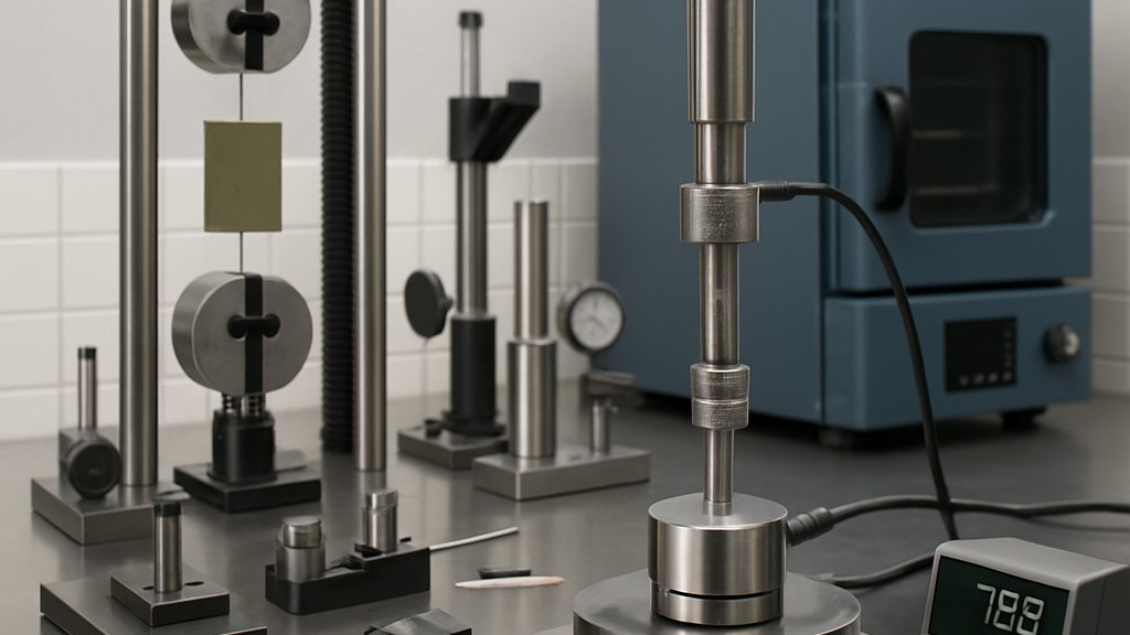
While the application should also be applicable to determining the thermal conductivity and thermal diffusivity of non-reactive materials, it has been found to be particularly useful in testing fire-resistant materials that are both reactive and undergo significant dimensional changes during high-temperature exposure.
This application is useful for testing materials in general, including composites and multilayer types. It is particularly useful for materials that undergo significant reactions, local dimensional changes, or both during exposure to high temperatures and are therefore difficult to evaluate using existing standard test methods such as ASTM C1113.
Performing the test over multiple heating/cooling cycles allows the impact of reactions, phase changes, and mass transfer of reaction gases (e.g., steam) on thermal performance to be evaluated. This practice has been found to be particularly applicable for testing fire-resistant materials.
For the purposes of this standard, the following terms and definitions apply:
In principle, an ingot made of a thermally conductive metal capable of withstanding high temperatures is surrounded by another material (sample) of uniform thickness whose thermal conductivity is significantly lower than that of the ingot. When the outer surface of this assembly is exposed to a temperature higher than that of the ingot, heat passes through the outer layer, causing a temperature increase within the ingot itself. The temperature increase of the ingot is controlled by the amount and rate of heat transferred to its surface (flux), its mass, and its specific heat capacity. Knowing these properties, the ingot's rate of temperature increase is directly proportional to the heat flux entering it. Therefore, under these conditions, the ingot becomes a flux-measuring device.
From this measured flux and the thermal gradient across the outer (sample) layer, the apparent thermal conductivity of the sample can be calculated. When the heat source is removed, the direction of heat flow reverses during natural cooling. Again, from the measured flux and thermal gradient, the apparent thermal conductivity can be calculated.
The ideal model described above is based on heat flow perpendicular to the sample and always passing through it. Deviations from the ideal can occur due to:
The user of this method should be aware that the contact resistance between the samples and the ingot may not always be negligible and, in some cases, can even be significant, possibly becoming the most significant source of uncertainty in the measurement. However, for low-density porous materials, it has generally been found that the contact resistance between the samples and the ingot can be neglected.
This method is suitable for many possible geometric configurations:
In short, ASTM E2584 outlines best practices and methodologies for reducing fire risks in photovoltaic (PV) panels and associated systems. This standard plays a crucial role in ensuring the safe deployment and operation of solar energy systems, particularly in residential, commercial, and industrial environments. The primary purpose of this standard is to provide guidance for minimizing fire hazards in PV systems. As solar energy technology continues to expand globally, ensuring these systems do not pose a fire risk has become a critical safety concern. This standard:
ASTM E2584 is an application standard, meaning it provides a guide rather than a specific test method. This standard covers:
With the increasing adoption of solar energy, the risk of electrical fires due to poor installation, component failure, or environmental factors is becoming significant. In this regard, ASTM E2584 supports:
Key elements for this standard include:
Ultimately, this standard helps ensure that solar installations are not only energy efficient but also safe. It significantly reduces fire-related risks across the board, protecting property, infrastructure, and lives.
Our organization, which has been supporting businesses across all sectors for years through a wide range of testing, measurement, analysis, and evaluation activities, has a strong team of employees who closely follow global developments in science and technology and are constantly improving themselves. In this context, we also provide testing services in accordance with ASTM E2584 Standard Practice for Thermal Conductivity of Materials Using Thermal Capacitance (Slug) Calorimeters.
To get an appointment, to get more detailed information or to request an evaluation, you can ask us to fill in our form and reach you.

