

The standard “ISO 14879-1 Implants for surgery - Total knee joint prostheses - Part 1: Determination of durability properties of knee tibial trays” developed by the International Organization for Standardization (ISO) describes a test method for determining the durability properties of tibial trays used to support and stabilize the plastic articular surface in knee joint prostheses under specified laboratory conditions. This method is applicable to tibial trays covering both the medial and lateral plateaus of the tibia. This test method is not applicable to tibial components manufactured solely from plastic materials. This standard does not cover methods for examining and reporting the final condition of the test specimen, which may be the subject of agreement between the testing laboratory and the parties submitting the specimen for testing. The correlation of test results with in vivo performance has not been established.
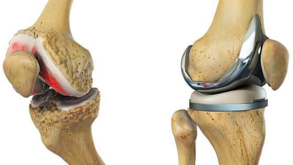
For the purposes of this standard, the terms and definitions from ISO 7207-1 and the following apply:
When testing, the test specimen is placed in a test fixture and one condyle of the tray is fixed in a way that it extends like a cantilever. A cyclic force is applied to the unsupported condyle via a spacer. The cyclic force is applied until the test specimen fails or until the selected number of cycles is reached. The specimen is then examined for defects resulting from loading.
Sample size and test conditions must be defined by the party submitting the samples for testing. Test conditions must include:
The test shall be conducted under force control using a minimum force corresponding to 10 percent of the maximum force in absolute terms. The ISO 21536 standard specifies a durability requirement considering at least five specimens exceeding 900 million cycles with a maximum force of 10 N. It is recognized that for some materials the environment can affect fatigue performance.
The tests use a testing machine with the following features:
A spacer is used to distribute the load and reduce wear between the test specimen and the load applicator. The load applicator is a rod with a 16 mm radius spherical recess at its end. It is recommended that the recess be made of metallic material. The load applicator must be able to move freely in the transverse direction of force application.
Among the numerous tests, measurements, analyses and evaluation studies that our organization has carried out for businesses in various sectors, our organization also provides testing services defined in the standard “ISO 14879-1 Implants for surgery - Total knee joint prostheses - Part 1: Determination of durability properties of knee tibial trays” with its trained and expert staff and advanced technological equipment.
To get an appointment, to get more detailed information or to request an evaluation, you can ask us to fill in our form and reach you.

