

For the purposes of this standard, the following terms and definitions apply:
Scratch testing involves drawing an indenter of known geometry through a coating-substrate system. In this test, the indenter is of known material, size, and geometry, such as a Rockwell cone diamond indenter. The test is performed over a specified length under a constant load. If the coating is removed from the substrate, the adhesion of the coating-substrate system can be assessed, and the adhesion level can be ranked against similar coating-substrate system combinations. If failure occurs only in a thermally sprayed ceramic coating, the inherent cohesion of the coatings is evident. If no failure is observed, the test load can be increased until coating failure occurs. Various coating failure modes during scratch testing are outlined in the standard appendix (Appendix A).
During scratch testing, cracks can form as a result of tensile stresses generated behind the indentation, which can balance the compressive friction stresses at the front. Crack formation can be detected by an acoustic emission sensor installed in the indentation holder of the scratch testing machine. Additionally, the tangential force between the indentation and the test surface can be monitored to provide further information about failure conditions. This tangential force, often incorrectly referred to as the friction force, is the result of both the friction between the indentation and the test specimen and the ploughing force required to deform the coating-substrate system.
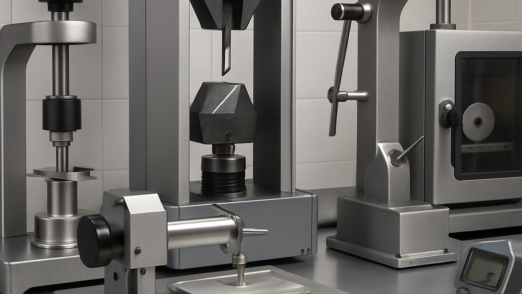
A scratch testing machine is a tool used to apply both the normal load and the driving force to firmly hold the indenter and produce scratches. A spring displacement is generally used to achieve the selected loading schedule. Magnetically driven assemblies are equally suitable. The scratch testing machine typically consists of a rigidly mounted diamond indenter with a Rockwell conical diamond geometry. Currently, a diamond indenter with a tip radius of 20 μm is recommended. The scratch testing machine used must be calibrated in accordance with the procedures outlined in ISO 20502.
The sample size for scratch testing varies because scratch testing machines have different sample holders. A sample size of 20 x 20 mm² is generally recommended . After spraying, coatings are cut perpendicular to the coating surface and embedded in a suitable material and polished. Using standard metallographic procedures, the cross-section of the coatings should be polished to a maximum of 0,5 µm before scratch testing (ISO 4287 standard). Since samples may be sensitive to heat or pressure, embedding in a cool mounting medium such as acrylic resin is recommended. Vacuum impregnation is generally not necessary. Before scratch testing, the test sample should be cleaned with alcohol or acetone and allowed to dry to remove surface contaminants such as oil, grease, and moisture. Fingerprinting should be avoided in the test area. The following information should be obtained from the coating manufacturer: substrate material and thickness, and coating material and thickness.
Scratch testing requires interaction between the indenter and the sample, which can be sensitive to environmental conditions. Therefore, temperature and relative humidity should be monitored and controlled to ensure repeatability. Recommended environmental conditions are: 22 degrees Celsius plus/minus 2 degrees Celsius and 50 percent plus/minus 5 percent relative humidity.
After the scratch test, the percentage of each failure mode present is determined using the captured images. Typical failure modes, including no cracks, cohesive cracks, and adhesive cracks, are shown in the standard appendix (Appendix A). Adhesive failure is indicated by the presence of cracks at the interface between the coating and another component of the coating-substrate system (bond coat/substrate or top coat/bond coat), while cracks within the coating are indicative of cohesive failure. If both failure types are present in a sample group, a failure mode is considered valid if it accounts for more than 30 percent of the observed failures. Examples of failures are shown in the table titled "Example of Failure Mode Evaluation."
Our organization, which has been supporting businesses across all sectors for years through a wide range of testing, measurement, analysis, and evaluation activities, boasts a strong team of employees who closely follow global developments in science and technology and are constantly improving themselves. In this context, we also provide testing services in accordance with the ISO 27307 Thermal Spray - Evaluation of adhesion and cohesion of thermal spray ceramic coatings by transverse scratch testing."
To get an appointment, to get more detailed information or to request an evaluation, you can ask us to fill in our form and reach you.

