

The standard “ASTM F3140-23 Standard test method for cyclic fatigue testing of metallic tibial tray components of unicondylar knee joint replacements” developed by the American Society for Testing and Materials (ASTM) describes the fatigue testing procedure for metallic tibial trays used in partial knee joint replacements. This test method includes procedures for performing fatigue tests on metallic tibial components using a cyclic, constant amplitude force. It is applicable to tibial trays covering the medial or lateral plateau of the tibia.
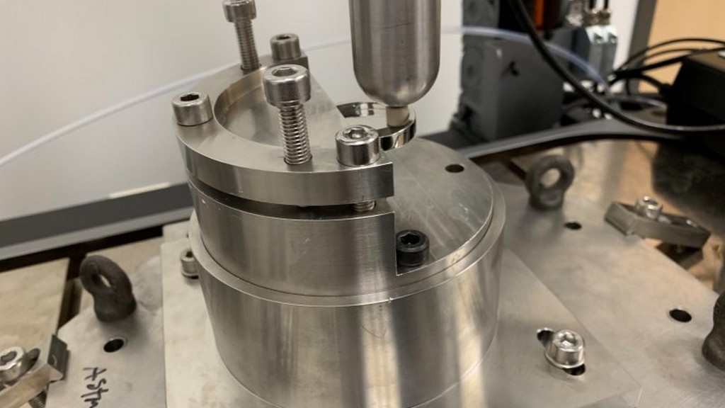
This test method may require modifications to accommodate other tibial tray designs. This test method is intended to provide useful, consistent, and reproducible information on the fatigue performance of metallic tibial trays with an unsupported midsection of the condyle.
This test method can be used to identify the effects of materials, manufacturing, and design variables on the fatigue performance of metallic tibial trays subjected to cyclic loading for a relatively large number of cycles.
In vivo loading of tibial tray designs will generally differ from the loading described in this exercise. The results obtained here cannot be used to directly predict in vivo performance. However, this exercise is designed to allow comparisons between the fatigue performance of different metallic tibial tray designs when tested under similar conditions.
To ensure that fatigue data on tibial trays are comparable, reproducible, and relatable across laboratories, it is essential to establish uniform procedures.
The selected test component must have the same geometry as the final product and must be in a machined and finished condition.
The tibial tray should be mounted as a three-point bending test. Care should be taken that the three-point bending fixture does not produce abnormal stress concentrations, particularly in the two reaction positions, which could alter the failure mode of the part. The reaction positions should contain 6 mm diameter cylindrical cylinders to avoid constrained forces that would increase the output load. Any deviation from the cylindrical cylinders or the recommended diameter should be justified in the test methods. A possible installation with walls in the anterior and posterior positions and in the medial lateral central positions is shown in the figure given in the standard. These walls are necessary to prevent possible rotation or expulsion of the implant during the relatively high frequency fatigue testing. Friction between the implant and the walls should be minimized.
The implant should be placed on the cylinders such that the distance between the centers of the cylinders is not less than 80 percent of the A/P distance as shown in the figure. The cylinder contact lengths should coincide with the A/P centerline to minimize rotational moments about the y-axis in the figure.
The implant should be supported sufficiently to allow bending forces that would cause test instability to be applied while minimizing the moment applied to the A/P or M/L axis. In some cases, this location may mask the worst M/L load location. An analysis should be conducted to find the physiological worst location and the fixture may need to be designed to accommodate this location.
The tibial tray should be positioned so that the anteroposterior centerline and the fixture centerline are aligned to an accuracy of 61 mm in the x-direction and 62 degrees in the xy-plane. If the tibial tray design includes a central spine or other projection, adequate clearance should be provided under the tray to prevent impingement of the spine during deflection.
Among the numerous testing, measurement, analysis and evaluation studies that our organization has provided for businesses in various sectors, our organization also provides testing services defined in the standard “ASTM F3140-23 Standard test method for cyclic fatigue testing of metal tibial tray components of unicondylar knee joint replacements” with its trained and expert staff and advanced technological equipment.
To get an appointment, to get more detailed information or to request an evaluation, you can ask us to fill in our form and reach you.

