ASTM F2706-18 Standard Test Methods for Occipital-Cervical and Occipital-Cervical-Thoracic Spinal Implant Constructs in a Vertebrectomy Model
The ASTM F2706-18 standard, "Standard Test Methods for Occipital-Cervical and Occipital-Cervical-Thoracic Spinal Implant Assemblies in Vertebrectomy Models," developed by the American Society for Testing and Materials (ASTM) , describes the materials and methods for static and fatigue testing of occipital-cervical and occipital-cervical-thoracic spinal implant assemblies in vertebrectomy models. For most combinations of occipital-cervical and occipital-cervical-thoracic spinal implant components, the test materials may be specific to the intended location and intended attachment method.
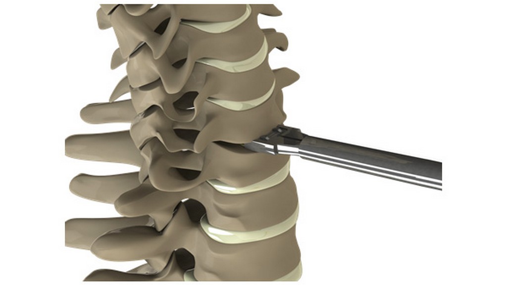
These test methods provide a basis for mechanical comparison among past, present, and future occipital-cervical and occipital-cervical-thoracic spinal implant assemblies. These methods allow comparison of occipital-cervical and occipital-cervical-thoracic spinal implant constructs with different application methods to the spine. These test methods are not intended to define performance levels as insufficient information is available to predict the results of using a particular device.
These test methods include guidelines for types of loads and methods of load application. Methods for three static load types and two fatigue tests are described for comparative evaluation of occipital-cervical and occipital-cervical-thoracic spinal implant assemblies.
These testing methods establish guidelines for measuring displacements, determining yield load, and evaluating the stiffness and strength of occipital-cervical or occipital-cervical-thoracic spinal implant assemblies.
However, it may not be possible to test some occipital-cervical and some occipital-cervical-thoracic spinal structures in all test configurations.
For the purposes of this standard, the following terms and definitions apply:
- The active length of the longitudinal member refers to the straight-line distance between the rotation centers of the test blocks.
- Block moment arm refers to the line perpendicular to the applied load between the insertion point of an anchor and the axis of the hinge pin.
- Compressive or tensile flexural stiffness is the compressive or tensile flexural yield force divided by the elastic displacement.
- Compressive or tensile flexural ultimate load refers to the maximum compressive or tensile force in the XZ plane applied to the occipital-cervical or occipital-cervical-thoracic spinal implant assembly. The ultimate load should be a function of the instrument, not the load cell or testing machine.
- Compressive or tensile bending yield load refers to the compressive or tensile bending force in the XZ plane required to produce a permanent deformation equal to 0,020 times the active length of the longitudinal member.
- The coordinate system/axes are defined as three orthogonal axes in the figures given in the standard.
- Displacement (mm) at 2 percent offset yielding refers to the displacement of a structure measured by means of an actuator that produces a permanent deformation equal to 0,020 times the active length of the longitudinal member.
- Elastic angular displacement (degrees) is the distance between the angular displacement at 2 percent offset yield, minus the angular displacement at 2 percent offset.
- The elastic displacement (mm) is the distance between the displacement at 2 percent offset yield minus the 2 percent offset displacement.
- Failure refers to permanent deformation resulting from fracture, plastic deformation, or loosening beyond ultimate displacement or loosening that renders the occipital-cervical or occipital-cervical-thoracic spinal implant assembly ineffective or inadequately resistant to loading.
- Fatigue life is the number of loading cycles of a specified character that the occipital-cervical or occipital-cervicothoracic spinal implant assembly can sustain before failure of a specified nature occurs.
- A hinge pin is a cylindrical rod that connects a test block to a side support. The top and bottom of the test structure are each secured by a single 9,6 mm diameter pin.
- The insertion point of an anchor is where the anchor is connected to the test block. The attachment points may deviate from these dimensions where the design of the occipital-cervical or occipital-cervical-thoracic spinal implant assembly or the manufacturer's surgical instructions for installation instruct otherwise.
Among the numerous testing, measurement, analysis and evaluation studies that our organization has provided for businesses in various sectors, our organization also provides testing services defined in the standard “ASTM F2706-18 Standard test methods for occipital-cervical and occipital-cervical-thoracic spinal implant structures in the Vertebrectomy model” with its trained and expert staff and advanced technological equipment.



