

The ASTM G76-18 Standard Test Method for Erosion Testing by Impact of Solid Particles Using Gas Jets, developed by the American Society for Testing and Materials (ASTM) , describes a test method for determining material loss by impact erosion of solid particles carried by gas using jet nozzle type erosion equipment.
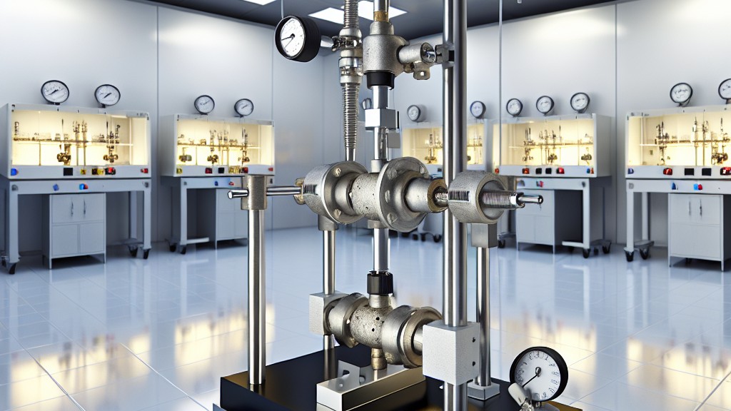
This test method can be used in the laboratory to measure solid particle erosion of different materials and as a screening test to rank the solid particle erosion rates of materials in simulated service environments. Actual erosion service involves a wide range of particle sizes, velocities, angles of attack, environments, and similar conditions. Therefore, any single laboratory test may not be sufficient to evaluate the expected service performance. This test method includes a well-characterized procedure for measuring solid particle impact erosion for which interlaboratory test results are available.
For the purposes of this standard, the following terms and definitions apply:
This test method uses a repeated impact erosion approach that involves a small nozzle delivering a gas stream containing abrasive particles and impinging on the surface of a test specimen. A standard set of test conditions is described. However, deviations from some of the standard conditions are permitted if described in detail. This allows laboratory-scale erosion measurements under a range of conditions. This standard describes test methods for preparing specimens, performing erosion exposure, and reporting results.
The importance of this test method in any overall measurement program for evaluating the wear behavior of materials depends on many factors related to the conditions of service applications. Users of this test method should determine the degree to which the results obtained correlate with results from field performance or with results obtained using other test systems and methods. This test method can be used to rank the wear resistance of materials under specified test conditions.
The apparatus used in these tests can abrade material from a test specimen under well-controlled exposure conditions. A schematic drawing of the outlet nozzle and particle-gas feed system is shown in the figure provided in the standard. Deviations from this design are permissible, but adequate system characterization and control of critical parameters are required. Deviations in nozzle design and dimensions should be documented. The nozzle length-to-diameter ratio should be 25:1 or greater to obtain an acceptable particle velocity distribution in the flow. The recommended nozzle consists of a 1,5-mm-long tube with an approximately 50-mm inner diameter manufactured from an abrasion-resistant material. Nozzle wear should be monitored during service and should not exceed a 10 percent increase over the initial diameter.
Required features of the instrument should include means for controlling and adjusting particle impact velocity, particle flux, and sample position and orientation relative to the impinging stream (impact angle).
Various means can be provided to introduce particles into the gas stream, including a vibration-controlled hopper or screw feed system. The system must provide a uniform particle feed and be adjustable to accommodate the desired particle flow values.
A method of measuring particle velocity shall be available for use with the abrasive equipment. Examples of acceptable methods include high-speed photography, dual spinning disks, and laser velocimetry. Particle velocity shall be measured at the location to be covered by the sample and under test conditions.
This test method can be used on a variety of sample sizes and configurations. A suitable sample configuration is a rectangular strip approximately 10 mm x 30 mm x 2 mm thick. Larger samples and other shapes may be used if necessary, but must be documented. The abrasive material used should be uniform in essential properties such as particle size, moisture, chemical composition, etc. Sampling of the material to obtain representative test samples should be in accordance with acceptable statistical practice. ASTM E122 applies.
This test method defines the following standard conditions.
Our organization, which has been trying to support businesses from every sector with its testing, measurement, analysis and evaluation studies carried out in a wide range for years, has a strong staff that closely follows the developments in the world in the field of science and technology and constantly improves itself. In this context, testing services are also provided to businesses in accordance with the standard "ASTM G76-18 Standard test method for conducting erosion tests by solid particle impact using gas jets".
To get an appointment, to get more detailed information or to request an evaluation, you can ask us to fill in our form and reach you.

