ISO 6336 Calculation of Load Capacity of Spur and Helical Gears
The standard “ISO 6336 Calculation of load capacity of spur and helical gears” developed by the International Organization for Standardization (ISO) consists of a series of standards organized under the same title:
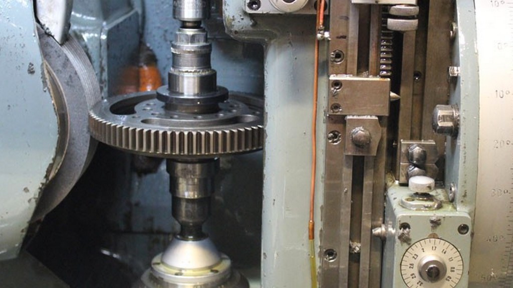
- ISO 6336-1 Part 1: Fundamental principles, an introduction and general influencing factors” provides the basic principles, an introduction and general influencing factors for the calculation of the load capacity of spur and helical gears. This standard, together with the other standards in the ISO 6336 series, provides a method by which different gear designs can be compared. It is not intended to guarantee the performance of assembled driven gear systems. It is not intended for general engineering purposes, but rather for use by the experienced gear designer who can select reasonable values for the factors in these formulas.
The formulas in the ISO 6336 series of standards are intended to establish a uniformly acceptable method for calculating the load capacity of cylindrical gears with straight or helical involute teeth. This series of standards includes procedures based on tests and theoretical studies referenced by each method. The methods have been validated for: normal operating pressure angles of 15 degrees to 25 degrees, reference helix angles of up to 30 degrees, and transverse contact ratios of 1,0 to 2,5. If this range is exceeded, the calculated results must be verified by experience.
The rating formulas in the ISO 6336 series of standards do not apply to other types of gear tooth deterioration such as plastic deformation, case crushing and abrasion, and do not apply under vibratory conditions where unpredictable profile deterioration may occur. This series of standards does not apply to teeth finished by forging or sintering, and to gears with poor contact patterns.
The impact factors presented in these methods constitute a method for estimating the risk of damage consistent with industry and empirical experience. It is possible that they are not completely scientifically accurate. Therefore, calculation methods from one part of the ISO 6336 series of standards are not valid in another part of the ISO 6336 series unless specifically referenced.
The procedures in the ISO 6336 series of standards provide rating formulas for calculating the load capacity for different failure modes, such as pitting, tooth root fracture, tooth flange cracking, fretting, and micropitting. At pitch line speeds below 1 m/s, gear load capacity is generally limited by abrasive wear.
The standard “ISO 6336-2 Part 2: Calculation of surface durability (pitting)” describes the basic formulas to be used in determining the surface load capacity of cylindrical gears with involute external or internal teeth. This standard contains formulas for all effects on surface durability for which quantitative assessments can be made. It is primarily applicable to oil-lubricated transmissions, but can also be used to obtain approximate values for grease-lubricated transmissions, as long as sufficient lubricant is always present in the network.
The formulas given are valid for cylindrical gears with tooth profiles compatible with the basic rack standardized in ISO 53. They can also be used for teeth equivalent to other basic racks where the true transverse contact ratio is less than 2,5. The results are in good agreement with other methods. These formulas are generally not directly applicable to the evaluation of types of gear tooth surface damage such as plastic yielding, scoring and abrasion. The load capacity determined by the allowable contact stress is called surface load capacity or surface durability.
- The standard “ISO 6336-3 Part 3: Calculation of tooth bending strength” describes the basic formulae to be used in the calculation of tooth bending stress for involute external or internal spur and helical gears having a minimum edge thickness of 0,5 ht for external gears and 1,75 mn for internal gears. In service, internal gears may experience failure modes other than tooth bending fatigue, i.e. fractures starting from the root diameter and propagating radially outwards. This standard does not provide adequate security against failure modes other than tooth bending fatigue. All load effects on tooth root stress are included as long as they are the result of loads transmitted by the gears and can be assessed quantitatively. The formulae given in this standard are valid for spur and helical gears having tooth profiles conforming to the basic racks standardized in ISO 53. They can also be used for teeth equivalent to other basic racks if the virtual contact ratio is less than 2,5. The load capacity determined on the basis of allowable bending stress is called tooth bending strength.
- The standard “ISO 6336-4 Part 4: Calculation of tooth flange fracture load capacity” describes a procedure for calculating the tooth flange fracture load capacity of cylindrical spur and helical gears with external teeth. It is not intended to be used as a rating method in the design and certification process of a gearbox. The formulas specified are valid for both driven and driven cylindrical gears. The tooth profiles correspond to the basic rack specified in the ISO 53 standard. They can also be used for teeth coupled to other racks where the true transverse contact ratio is less than 2,5. The procedure has been validated for carburized gears and the formulas of this standard are only valid for carburized gears with properties within the specified limits. This standard is not applicable for the evaluation of gear tooth damage types other than tooth flank fracture.
- The standard “ISO 6336-5 Part 5: Strength and quality of materials” describes the contact and tooth root stresses and gives numerical values for both limiting stress numbers. This standard specifies the requirements for material quality and heat treatment and comments on their effects on both limiting stress numbers. The values given in this standard are suitable for use in conjunction with the calculation procedures provided in ISO 6336-2, ISO 6336-3 and ISO 6336-6 and in the application standards for industrial, high-speed and marine gears. They are valid for all gears, basic rack profiles, profile dimensions, design, etc. covered by these standards. The results are in good agreement with other methods for the range specified in ISO 6336-1 and ISO 10300-1.
- In the standard “ISO 6336-6 Part 6: Calculation of service life under variable load”, It describes the information and standardized conditions required for calculating the service life of gears subjected to variable loading for only pitting and tooth root bending strength or the safety factors for the required life.
- The standard “ISO 6336-20 Part 20: Calculation of wear load capacity - Flash temperature method” describes methods and formulas for assessing the risk of wear based on Blok’s concept of contact temperature. The basic concept is valid for all machine elements with moving contact areas. The flash temperature formulas are valid for operating conditions characterized by a band-shaped or nearly band-shaped Hertzian contact area and sufficiently high Péclet numbers.
- In the standard “ISO 6336-21 Part 21: Calculation of friction load capacity - Integral temperature method”, The integral temperature method used in calculating the wear load capacity of cylindrical gears is explained.
- In the standard “ISO 6336-22 Part 22: Calculation of micropitting load capacity”, A procedure for calculating the micropitting load capacity of cylindrical gears with external teeth is described. This standard was developed on the basis of testing and observation of oil-lubricated gear transmissions with modules between 3 mm and 11 mm and pitch line speeds between 8 m/s and 60 m/s. However, the procedure can be applied to any gear pair for which suitable reference data are available, provided that the criteria specified in the standard are met. The formulae specified are valid for driven as well as driven cylindrical gears having tooth profiles conforming to the basic rack specified in ISO 53. They are also valid for teeth equivalent to other basic racks where the virtual contact ratio is less than 2,5. This standard does not apply to the evaluation of types of gear surface damage other than micropitting.
- In the standard “ISO 6336-30 Part 30: Calculation examples for the application of ISO 6336 parts 1, 2, 3, 5”, worked examples are presented which apply only approximate methods for the determination of certain influential factors such as the dynamic factor Kv and the load distribution factors KHα, KHβ etc. The full analytical calculation procedures are provided in the referenced parts of the ISO 6336 standard. Worked examples covering more advanced analysis techniques and methods are not applicable to this document. The example calculations presented in this standard are provided for guidance on the application of ISO 6336-1, ISO 6336-2, ISO 6336-3 and ISO 6336-5. None of the values, safety factors or data presented represent recommended criteria for the actual gear.
- The example calculations presented in the standard “ISO 6336-31 Part 31: Examples of calculation of micropitting load capacity” are provided solely for guidance on the application of the ISO/TS 6336-22 technical specification. None of the values or data presented in applying this procedure should be used as material or lubricant allowances or as recommendations for micro geometry in actual applications. The required parameters and the allowable film thickness values should be determined for a specific application in accordance with the procedures defined in the ISO 6336-22 standard.
Among the numerous testing, measurement, analysis and evaluation studies that our organization has carried out for businesses in various sectors, it also provides testing services defined in the “ISO 6336 Calculation of load capacity of spur and helical gears” series of standards with its trained and expert staff and advanced technological equipment.



