NASM 1312-11 Fastener Test Methods - Method 11 Stress Fatigue
The “NASM 1312-11 Fastener Test Methods - Method 11 Stress Fatigue” standard, a National Aviation Standard, has replaced the “MIL-STD-1312/11A Military Standard: Fastener Test Methods (Method 11) Stress Fatigue” standard developed by the United States Department of Defense.
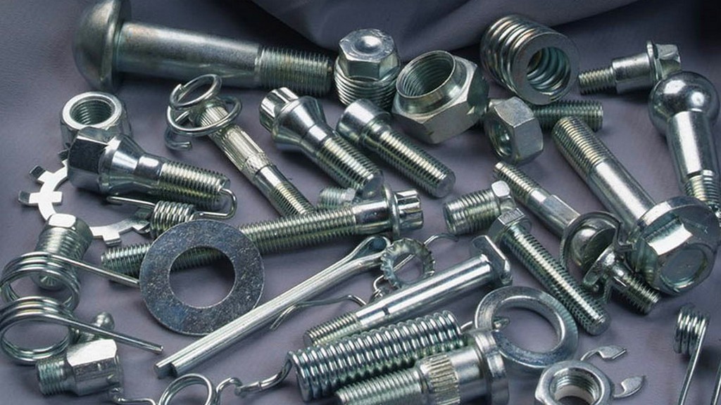
The NASM 1312-11 standard describes the procedure and equipment to be used in tensile fatigue testing of bolts, screws and nuts at room temperature.
The general requirements in this standard are as follows:
- Fixtures: A typical test fixture arrangement for fatigue testing of fasteners is shown in the figures provided in the standard. The procedure for verifying proper fatigue testing machine and fixture alignment and cyclic load application for the testing machine is included in the appendix to the MIL-STD-1312 standard (Appendix C).
- Static alignment: The static alignment of each fatigue testing machine should be verified to ensure that it meets the alignment requirements of MIL-STD-1312 Annex C.
- Spacer: A spacer can be used under the head of protruding head fasteners to provide clearance for the head-body corner radius of the fastener. Flat spacers can be used under the nut.
- Test nuts: Fatigue test nuts shall conform to the figures given in the standard. Threaded adapters may be used on shear fasteners of half an inch diameter or on tension fasteners that are too short to be tested with nuts in existing fixtures. Locking devices are not permitted. Type A or B nuts may be used to test bolts below 260 ksi. A fatigue test nut may be reused for more than five tests as long as the nut meets the dimension requirements and has not been damaged in a previous test, and the same nut is used to test the same group of bolts. Only unused nuts shall be used for referee testing.
- Test bolts: Test bolts or studs should not be reused.
- Limitations: Universal joints or spherical sockets should not be used anywhere in test fixtures.
- Fixture alignment: Fixtures used must be capable of holding fasteners in accordance with the alignment requirements specified in MIL-STD-1312 Appendix C.
- Threaded adapters: The hardness of threaded adapters shall be as specified in the figure given in the standard.
- Bolts: Protruding head pull bolts are tested using fatigue test nuts or threaded adaptors as indicated in the standard. Flat head bolts and protruding head shear bolts are tested using fatigue test nuts or threaded adaptors. Threaded adaptors are replaced when damaged by visual inspection or when out of tolerance. When adaptors are used for referee tests, they shall be unused adaptors. Fatigue tests shall not be performed on cross-drilled threaded parts. For bolts with coarse or special threads, the fatigue test nut shall be as specified in the supply specification. The minimum recommended grip length for test bolts shall be twice the nominal diameter.
- Testing of nuts: Nuts are tested on bolts as specified in the supply specifications. Nuts are assembled on bolts with at least two full threads open between the nut and the end of the bolt. A sample of each batch of bolts or studs used for testing nuts is first tested in accordance with this test method using the test nuts shown in the figure to determine their reliability.
- Nut test results: Fracture at the threads of the bolt or nut and failure to support the test load constitutes a valid test result. Fracture of the bolt elsewhere is not considered a valid test result and will be repeated using a new nut and bolt.
- Tension bolts: Tension bolts should be installed so that at least two and at most three threads are exposed between the nut bearing face and the bolt thread outlet.
- Shear bolts: Shear bolts should be installed so that at least half and at most one thread is exposed between the nut bearing face and the bolt thread exit.
- Flat head bolts: Flat head bolts are checked for proper bearing between the bolt head and the bottom cover on which it is to be tested. There should be no contact at the head-shank corner radius creation.
- Torque: There should be no tensile stress on fasteners due to torque or other assembly procedures.
- Load level: The fatigue test load shall be as specified in the applicable supply document or product specification.
- Load ratio: Unless otherwise specified, the low load should be one tenth of the high load level.
- Test speed: The test speed should not exceed 12.500 cycles per minute. When testing high-strength fasteners at high frequencies, excessive heat may be generated. In this case, the test speed should be reduced to ensure that the maximum (test fastener) temperature does not exceed 66 degrees.
Among the numerous testing, measurement, analysis and evaluation studies that our organization has provided for businesses in various sectors, it also provides testing services defined in the “NASM 1312-11 Fastener Test Methods - Method 11 Tension Fatigue” standard with its trained and expert staff and advanced technological equipment.



